ELECTRICS
My knowledge of electrical matters is at the level of water running through pipes. I can cope with DC but AC is a closed book. Any mention of micro-chips causes my brain to close down. Consequently the electrical arrangements on my layout are very basic. My boyhood heroes Edward Beal and John Ahern would feel quite at home operating it. The only modern bits of kit are two feedback controllers and a couple of CDU’s.
The main line consists of two circles, each splitting into a four track storage yard at the rear. All turnouts are operated by surface mounted PECO point motors. Each circle is controlled from an H&M Duette controller which has an H&M switch unit fixed to one end of it. The innards have been removed from this and replaced with a CDU, whilst a diagram of the fiddle yard covers the front of it. Studs set into the diagram connect to the point motors which are energised by an electric probe consisting of a piece of flexible wire. A route is set up simply by tracing along it with the probe and touching it onto every stud on the route. Home signals at each tunnel mouth are operated on the same system.
The operator has to pay attention because power has to be increased as trains round the end curves to overcome the increased friction. It is also possible to stop trains at the signals, in front of the audience and, with a quick twist of the control knob, induce a bit of wheel slip just like the real thing. I once tried feedback controllers on the main line but found they prevented wheel slip, so I gave up the idea.
I do use feedback controllers on the loco shed as I want slow, steady running. The shed is divided into two electrical sections, or cabs, each with its own feed and each is connected to both controllers via a double pole double throw switch (ex GPO). Each cab can be run separately or both can be connected to one controller. They are normally both run from one controller because there is not room inside the layout for three operators.
All turnouts in the shed yard are operated by PECO point motors, again energised by the stud and probe method. Three ancient H&M solenoid operated auto cut-outs protect the two controllers and the point operating circuit. They give instant notice of a short and are easily reset once the fault has been cleared.
All of the wiring is on top of the baseboards. Most of it consists of multi-way, multi-coloured, flat form cable, an admirable product which it seems is no longer available. In some places I have used thin, flat, self-adhesive, copper strip. The problems with this material are in getting it around corners and in getting the ballast to stick to it. Electrical connections are made using D connectors or DIN plugs and I always ensure that the mains feed is through an RCD.
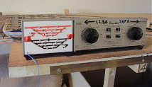
The ancient H&M Duette controller which runs the two main lines
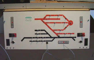
The panel that controls the loco shed
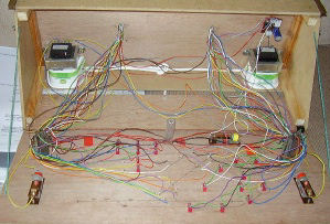
The inside of the loco shed panel. The margarine tubs screen the HV feeds to the transformers
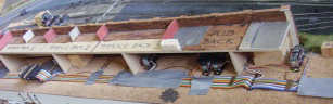
Wiring and point motors hidden behind the rear retaining wall